Thursday, January 29, 2009

Back in Action

At long last, I was able to finish installing the new drivetrain, this time on the left foot.


As I was testing on the carpet, I ran R2 backwards and forgot that I had removed the wedges that keep the feet from pivoting. That caused the back of the center foot shell to get wedged into the carpet and develop a partial crack on a seam that will be easy to repair. It didn't even break the seam all the way, and the shell is still very solid. The hard part will be getting the center foot off, as the ankle bolt hole is crammed in there pretty good. It can wait for a little while.

Anyway, R2 is running great with the new drivetrains on the feet, at least for the few minutes I could run him in the confined space of my home.

Thanks again to Mike Senna for not only coming up with the drivetrain design, but for all the work and help he provided to make the drives a reality.

Wednesday, January 28, 2009

Foot Shell Work

Well, I hoped to have both drivetrains on the droid tonight, but I didn't quite get there.

I found one of the foot shells was getting too close to the chain on the largest gear.


I marked the area, and buzzed it with the Dremel drum sander.


The other problem I had was that one of the foot shells was sagging on the drivetrain. I cut a couple of small pieces of PVC and glued them to the shell to prop it up.


I did manage to get the right drivetrain back on the droid and it's happy. Hopefully tomorrow I can do the same for the left foot.

Tuesday, January 27, 2009

Wired Up and Tested NPC Motors

Tonight I was able to wire up my NPC motors and test them out.

First, I had to fit each motor to its foot shell, to determine where to clip wires and solder connectors.


Next, I soldered the connectors to the NPC wires.


Each solder joint was covered in shrink tubing.


As I went to put the new drivetrain on the droid, I managed to knock out one of bushings where the ankle bolt hole goes on the left drivetrain, thus derailing my chances of running the droid tonight. :(


I scuffed up the area, applied a generous amount of JB Weld to the bushing, and tapped it back in with the hammer.


Meanwhile, back on the droid, I decided to test the right drivetrain.


I found that it spun backward, which wasn't much of a surprise. There was a 50/50 chance that the NPC motors were going to connect the opposite way from the Trico motors. I swapped the positive and negative wires on the terminals on the Vantec RDFR23 speed controller, and all was well.


I tested the left motor to see if it would spin backward, and it did, so I also swapped its wires on the speed controller and it now turns properly.

Tomorrow I hope to fit the left drivetrain on the droid, and then start doing some minor repairs to things that I knocked off during this operation. Hopefully everything will be done by the end of the week and R2 will be back in action.

Monday, January 26, 2009

12 Volt Conversion

At long last, today was the day I wired up my droid for 12 volt operation.

I needed to solder three wires together for the positive connection, and another three wires together for the negative. Two of the three wires come from the connectors that go to the two banks of batteries. The third wire on the positive connection goes through the 30 amp circuit breaker and on to the positive bus bar, while the third wire on the negative connection goes to the on/off switch, and on to the negative bus bar.

My soldering skills haven't gotten much better over the years, but I managed to solder the positive connections together.


Likewise, I soldered the three negative wires together. Not pretty, but I tugged on the wires and they held solidly.


I wrapped everything up tight with electrical tape. I wanted to top this off with shrink tubing, but I didn't have any with a large enough diameter.


With the batteries disconnected from the droid's electronics, I powered up and tested the voltage. 12.81 volts, looks good!


I got the wiring settled in the droid and connected to the bus bars, and flipped the switch. Everything that was connected (speed controller, Keycoder, sound card, dome drive) worked fine. The fact that I didn't blow anything up (yet) is major progress for me.

For now I have the H&A drivetrain on the droid, tomorrow I hope to wire up the NPC motors and try them out for the first time on the droid.

Sunday, January 25, 2009

Filed and Pinned Gas Pipe

Today I spent some time preparing the gas pipe that joins the wooden legs together for use with the new, stronger NPC 2212 motors.

The first thing I did was file a flat spot on the outer gas pipe, where the angle iron rests upon it. (More on that a little further down.)


Next, I drilled four 1/8" holes, ninety degrees apart, on each gas pipe flange.


Next, I took some 1/8" diameter, 3/4" long steel pins that I usually use to pin the shaft adapters to the Saturn motors, and used them to pin the gas pipe to the flange. The gas pipe is already JB Welded on, but this provides extra reinforcement. The pins are also JB Welded on. I made sure the gas pipes could still slide all the way into each other without hitting the pins first, by inserting all the bolts into the gas pipes that I worked on yesterday.


I squeezed in a couple of minutes to paint the channel pieces of the new drivetrain white. Something went a little wrong with one of the corners, I will go back and touch that up soon.


Finally, I started putting the droid back together. The angle iron now rests on the flat spot on the gas pipe.


I hope to return to the rewiring work tomorrow.

Saturday, January 24, 2009

Undid 24 volt Wire-Up, More Bolts for Gas Pipe

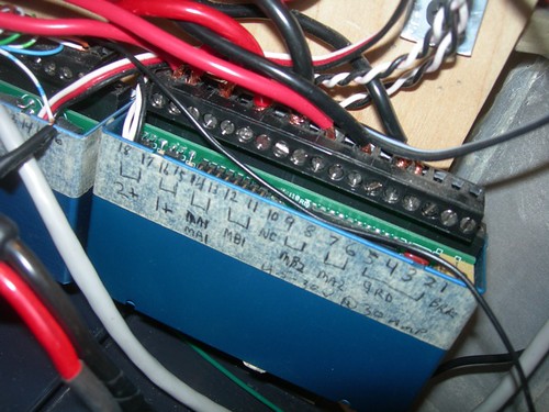
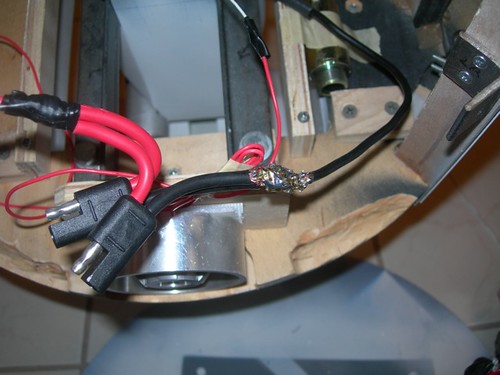
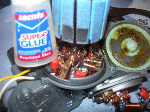
Today I started undoing the 24 volt path in my droid, as I am migrating to a 12 volt system.

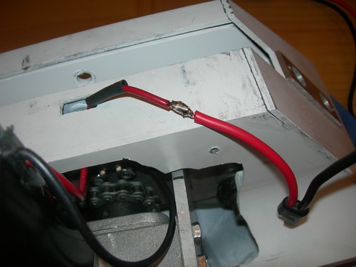
The only thing that really makes it 24 volts is the fact that two pairs of 6 volt batteries that are wired in series are themselves wired in series, by connecting the negative pole of one battery bank to the positive pole of the other. Red to black makes this connection.


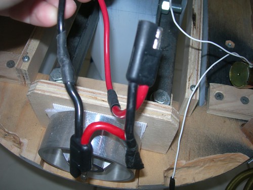
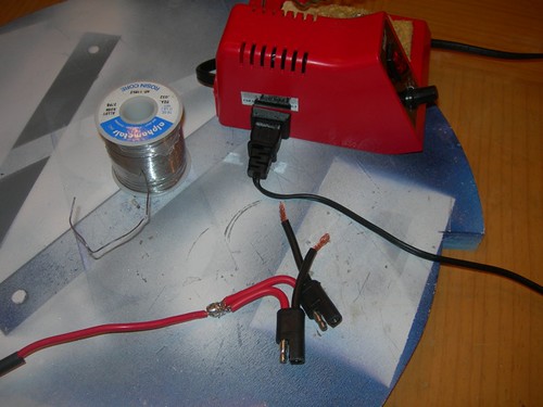
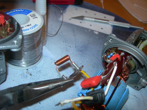
Unsoldering the wires undoes it.


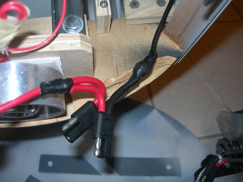
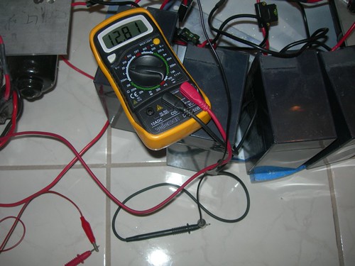
I now need to connect negative to negative and positive to positive, in order to wire these two 12 volt banks of batteries in parallel. I thought I was going to get to that today, but it didn't happen.

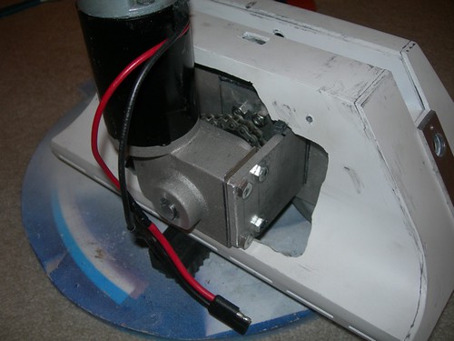
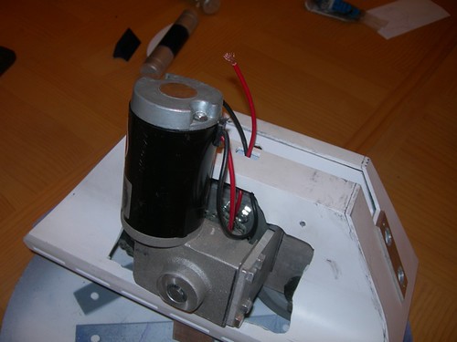
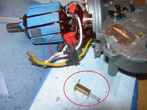
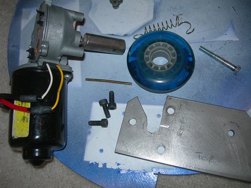
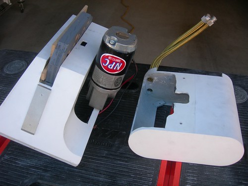
Instead I ran to Orvac Electronics and picked up a 30 amp circuit breaker, to replace the 25 amp circuit breaker I had been using with the Saturn wiper motors. The NPC 2212 motors can draw more current, and I don't want my circuit breaker tripping unnecessarily. I also have the batteries fused for 30 amps, but I'm wondering if this should be increased, to say 35 amps so that the circuit breaker will trip before the fuses blow.

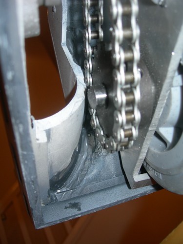
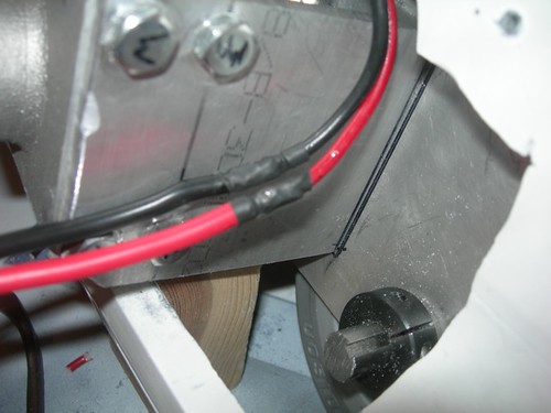
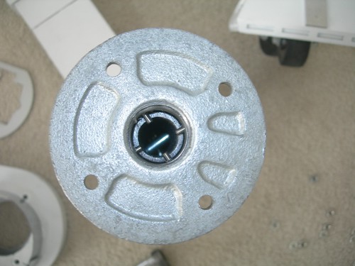
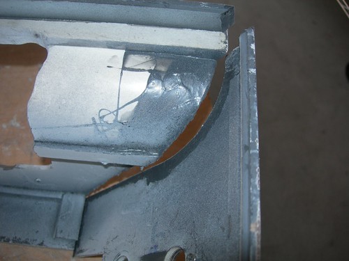
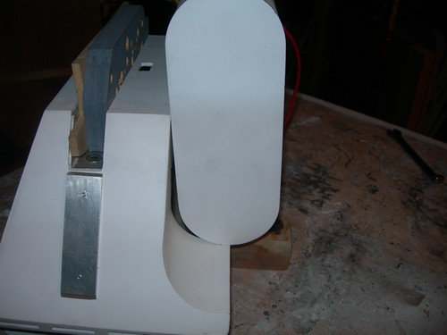
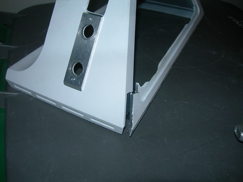
The next item of business was to fix a long standing annoying issue, namely the wiggle room between the gas pipes that connect the legs together.

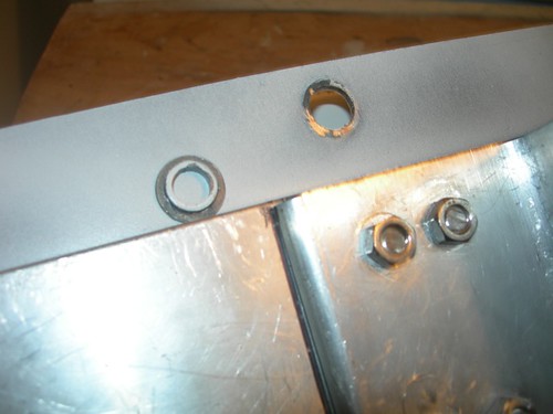
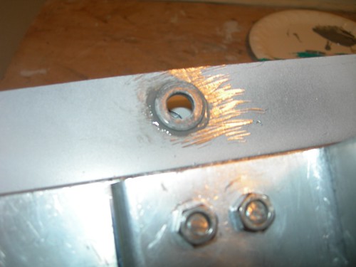
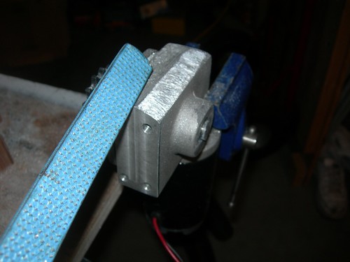
I clamped some flat boards to the legs to ensure that they were pointing in the same direction, in preparation for drilling more holes for the bolts that lock the gas pipes together.


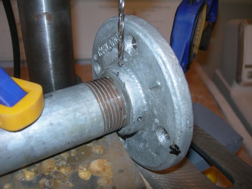
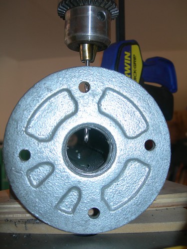
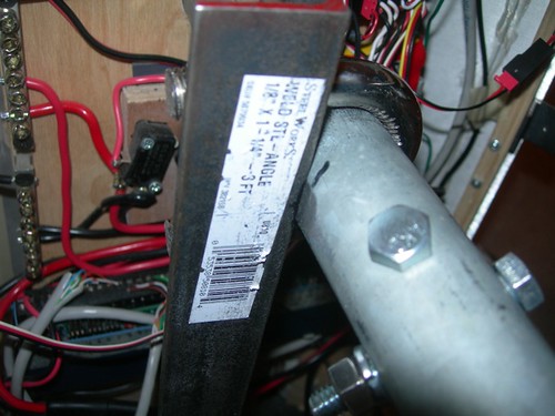
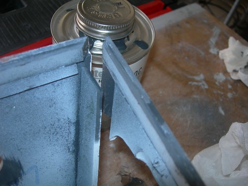
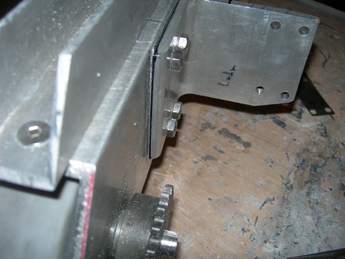
Then, it was over to the drill press, where I clamped the work down, and even clamped the gas pipe to the drill press, to keep the drill press and gas pipe from vibrating apart from each other.


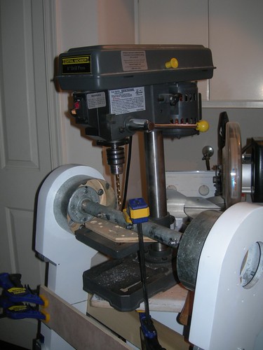
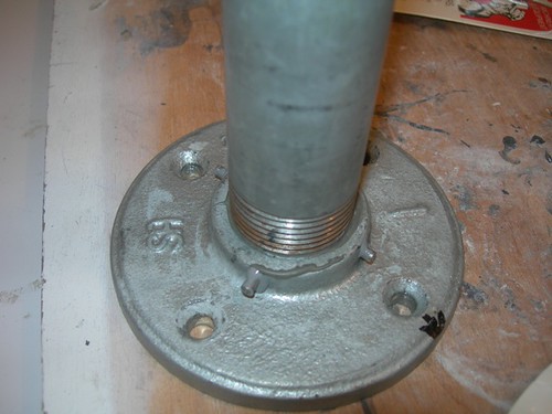
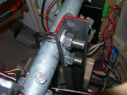
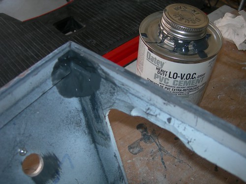
What were two bolts are now seven! The wiggle seems to be gone, although I won't be positive that this issue is resolved until I get the droid back together again.


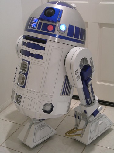
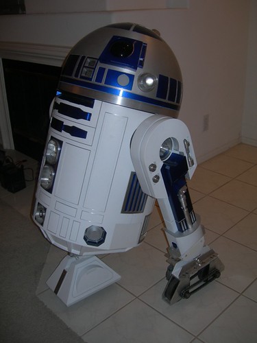
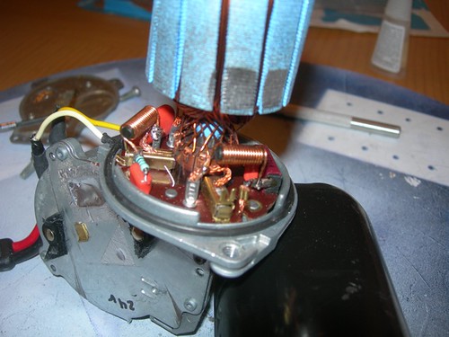
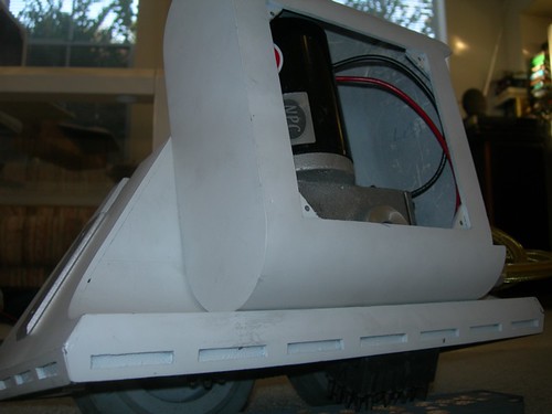
Speaking of which, the poor droid is in an exploded state once again.


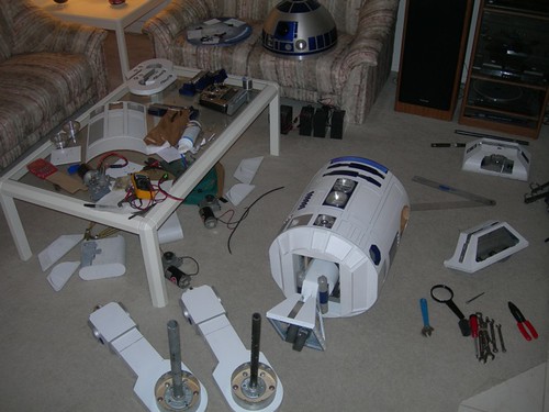
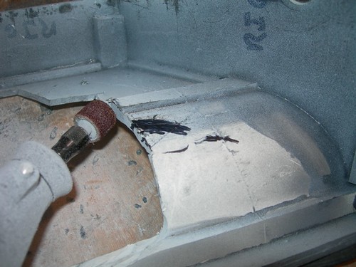
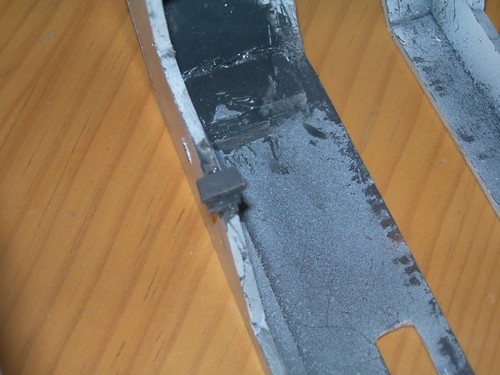
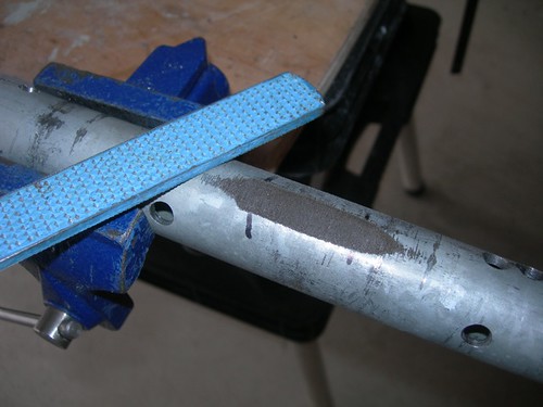
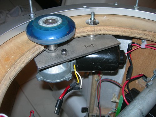
I need to file a flat spot on the outer gas pipe to help the angle iron and U-bolt lock in the 36-degree angle of tilt, because Mike reports that the angle of tilt can be altered by the power of the NPC motors. I also need to finish the 12 volt conversion. I hope to make progress on both of those tomorrow.

Thursday, January 22, 2009

Dome Drive Motor Transplant

Well, I found myself up a creek, and I had to figure out how I was going to paddle out of it.

The problem is that I'm moving my droid from 24 volts to 12 volts, due to the new 12 volt NPC motors I will be using soon. I had already converted every one of my Saturn motors to 24 volts, including the dome drive, using Alex Kung's tutorial. That fact in and of itself isn't so bad, but the problem is that I discarded all of the parts that get removed during the conversion, leaving myself in a bind to undo the conversion.

I finally decided to attempt to use one of my failed Saturn motors as an organ donor, as it has been donated to medical science at this point.


Only three parts need to be harvested from the failed motor. Two of the parts are shown here, the brush housing with spring, and the brush. (At least, I think that's what these parts are.)


I wasn't able to attach the brush housing to the small electronics board the way it's meant to be attached, so instead I used superglue to glue down the housing, with the spring and brush already inside. I can only hope this will stay attached indefinitely. The bond certainly seems strong as of now.


The third part I needed from the failed Saturn motor was a coil.


Now everything I needed from the bad motor has been transferred and soldered to the dome drive motor.


Time to close it up and test it out with a 12 volt battery.


It worked!!

I think I'm in business, and I'm ready to convert the droid itself to 12 volts. I currently have four 6-volt batteries, they are paired up in series of twos for 12 volts, and then the two pairs of 12 volt battery pairs are themselves paired up in series to provide 24 volts to the droid's main power bus. (I also have a 24->12 volt adapter for my sound card and mist solenoid.) I will wire up the two banks of 12 volt battery pairs to be in parallel rather than in series, and then my droid will be a 12 volt droid.

Tuesday, January 20, 2009

Disassembled Dome Drive

This hardly qualifies as building, in fact it's taking things apart.

In preparation for a new Saturn motor that will run at 12 volts, I removed the 24 volt motor that runs my dome. The dome drive is held on using a bolt from underneath. The bolt goes through a small piece of bar, from which the motor hangs.


A 1/8" diameter brass rod locks the dome wheel onto the shaft adapter. Fortunately, I made the rod removable with pliers, so I can migrate the dome wheel to the new motor.


It's all apart, awaiting the new motor.

Sunday, January 18, 2009

Left Foot Shell Repair, Bushing for Drivetrains

This morning I had some time to repair the damage I accidentally inflicted on the left foot shell last night, when it fell from the table as I was sawing some steel.

There were two main areas that separated. The first was along the curved area of the foot shell.


I generously applied some Oatey PVC glue, and things seemed to be holding.


The other area of damage was near the bottom edge on the other side.


Again, I applied PVC glue, let it set, and things seem better.


Later in the day, once the glue had dried, I fitted everything for the left foot. It all came together nicely, I was able to fit the motor into the battery box without having to cut a visible area of the bottom of the box.


There remained one last step for the drivetrains, inserting the 1/2"->3/8" bushing in the holes in the channels, where the ankle bolts will go.

I applied JB Weld to the bushings and pressed them into place.


What's next? Well, I still need to do a few things before I'm ready to try out the new drivetrain. Among them, I need to convert the whole droid over to 12 volts. The only item in my droid that is set up to run exclusively at 24 volts is the dome drive. I hope to address that later in the week.

Another task that awaits is the drilling of a few more bolts through the gas pipes, to lock them together better. Right now there is a little play, that causes R2 to sometimes "shrug" as he starts to move.

Finally, I need to grind a flat spot onto the gas pipe, to help the U-bolt grip around it tightly. Mike Senna reports that the NPC motors are powerful enough to out-muscle the U-bolt, and cause the angle of tilt to change when R2 encounters bumps and obstacles.

Saturday, January 17, 2009

Fit Left Drivetrain to Foot Shell

Time to get that left drivetrain fitting into the foot shell.


I marked areas on the foot shell that needed material removed in order for the NPC motor to fit, and then I made room with the Dremel drum sander. A pencil line demarcates the area that can be seen by the outside world. Do not cross.


Iterative fittings showed the battery box bumping into the bottom and top of the motor, so I filed the heck out of those areas.


Even with all that filing, the battery box still didn't want to fit correctly.


I slid a piece of paper around to figure out where the battery box was making contact with the motor. The bottom was clear, but the top still seemed to have an issue.


I determined that I needed to shim the motor mount about 1/32" from the drivetrain body. I took one of my shims used for mounting the motor to the motor mount, and used it to temporarily shim the motor mount from the drivetrain body. I put everything back on, and it all fit!


I ran to Lowe's as they were closing and picked up a small 1/32" steel sheet, and started cutting it to size.


Just about at that point in time, a minor disaster occurred. I had left the foot shell on the bench that I was using to cut the steel, and all the shaking while using the saw caused the foot shell to fall to the floor. Ouch!


Well, I should be able to glue that up tomorrow, but I wasn't able to do a final test fit, although I think it everything should still fit okay. The thin shim is in place, although it is hard to see.


I'll be pressed for time tomorrow, but hopefully I can finish the fitting and move forward.