Monday, November 29, 2010

Started Drilling Foot Strips

Tonight I started drilling and mounting of the first of the six foot strips.

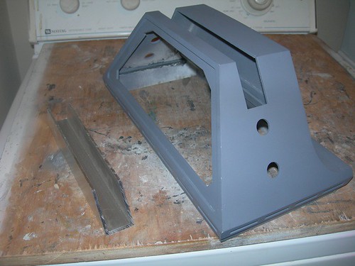
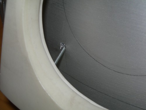
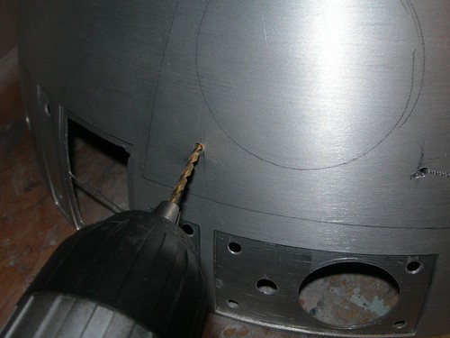
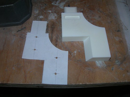
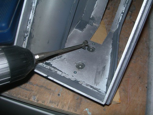
First, I marked where I wanted the mounting screws to be located on the foot shell.


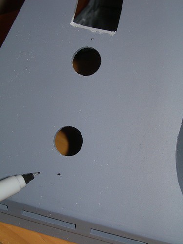
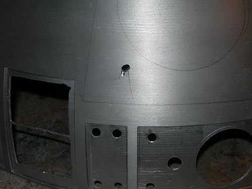
Then, I drilled for a #4 screw.


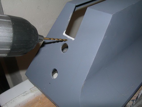
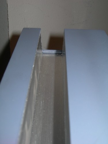
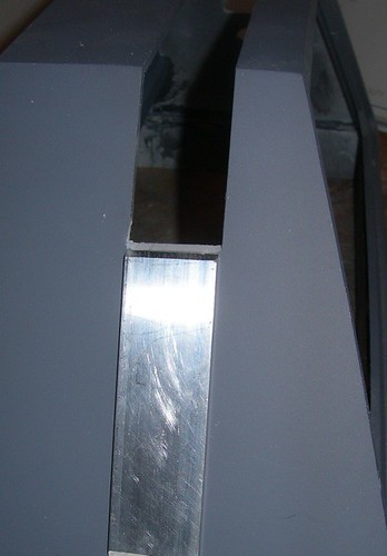
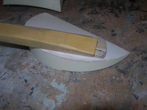
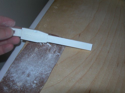
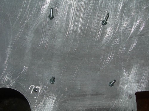
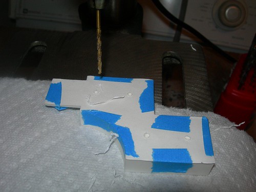
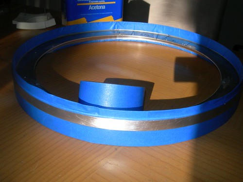
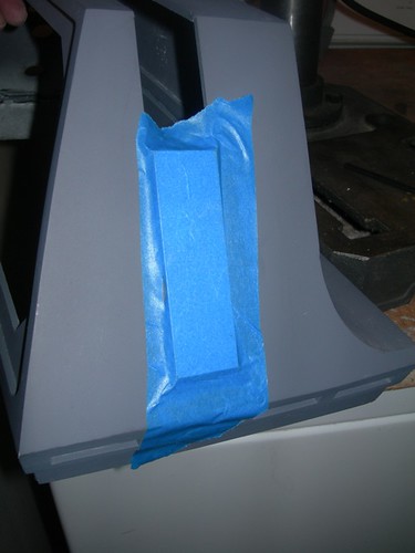
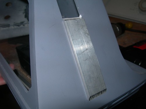
Next, I taped the foot strip so that it would be centered below the channel on the foot shell, and drill pilot holes from behind with the hand held drill.


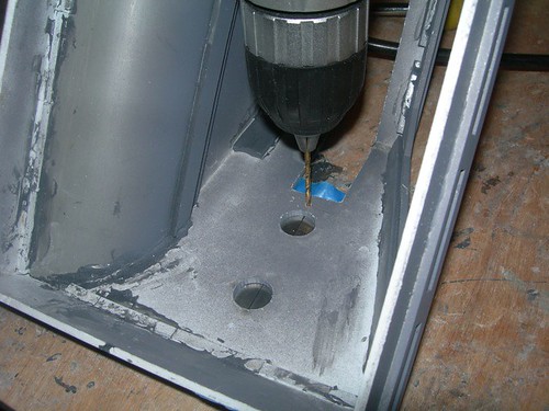
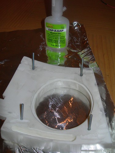
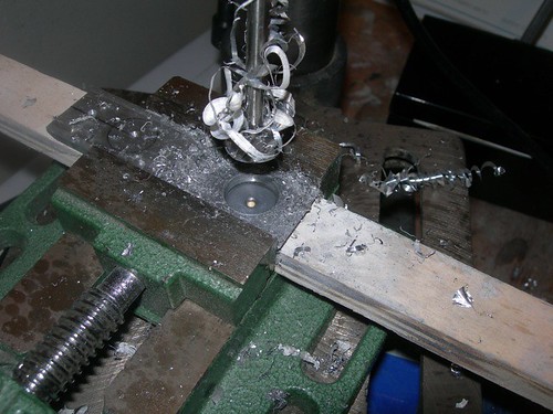
I used the drill press to drill about 2/3 deep into the back of the foot strip. I don't want to go all the way through if I don't have to. I then tapped the hole for a 4-40 screw. I think the hole is deep enough that the screw will have enough threads to keep the foot strip tight against the foot shell.


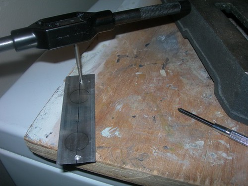
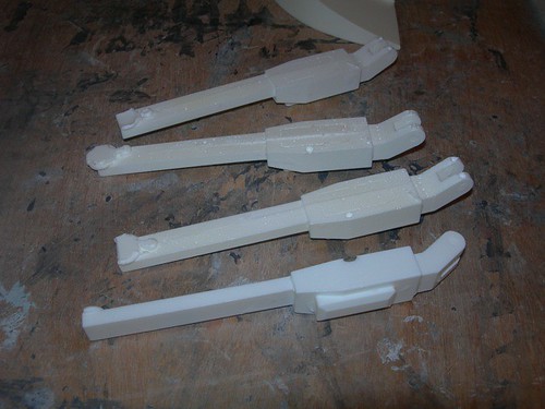
I repeated for the other screw, and the foot strip seems to be holding well.


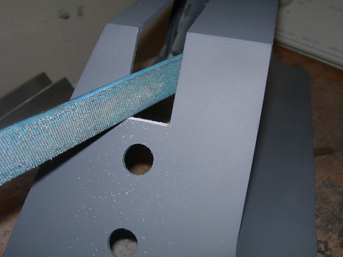
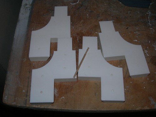
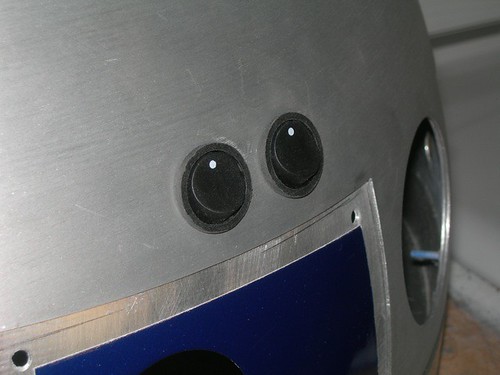
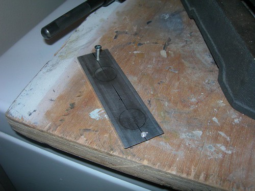
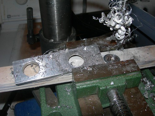
Next, I used the pre-cut holes in the A&A foot shells to determine where to drill the holes in the foot strip for the knurled hose fittings. I drilled a couple of pilot holes while the foot strip was screwed down in place.


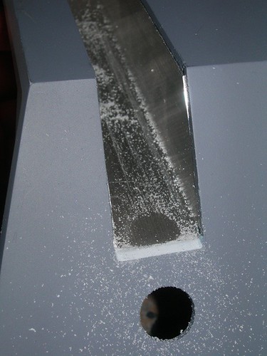
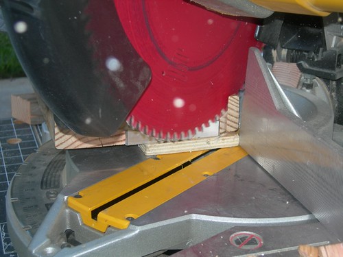
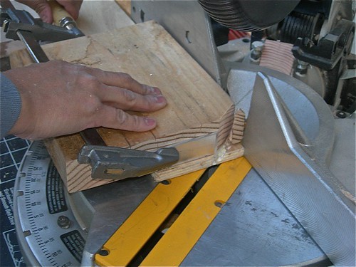
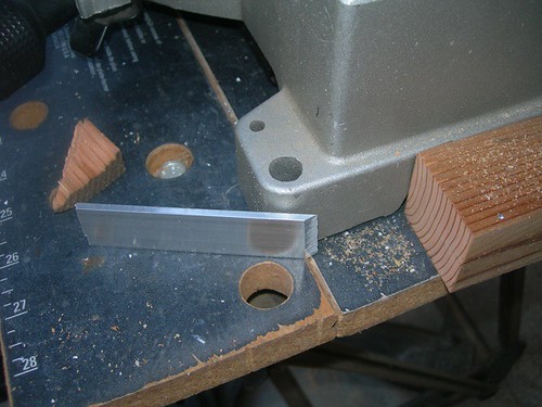
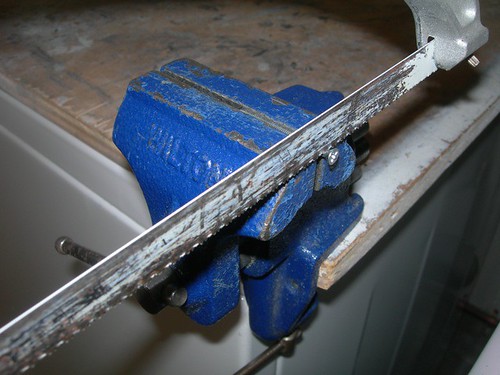
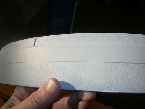
I then removed the foot strip from the foot shell and drilled the pair of 5/8" holes on the drill press, using WD-40 to keep the aluminum foot strip and drill bit lubricated.


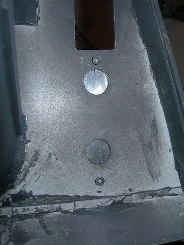
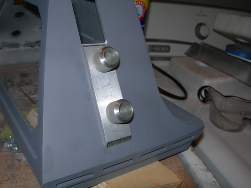
Finally, it was time to try it out on the foot shell. The holes seem to match up, although I think the holes are slightly off-center on the A&A foot shell. I may decide to drill the next one such that the holes are more perfectly centered on the foot strip, even if that does not match the holes in the foot shell.


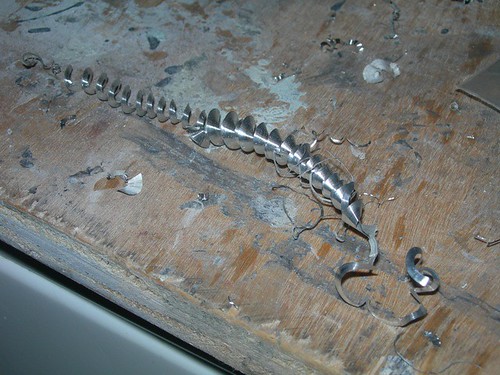
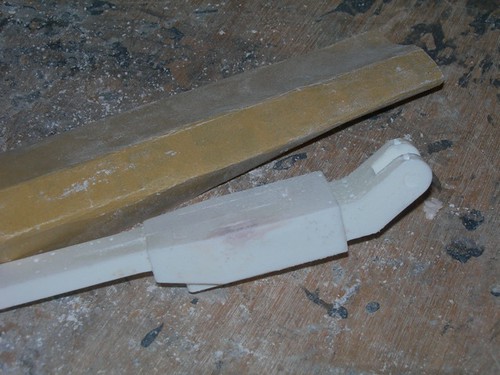
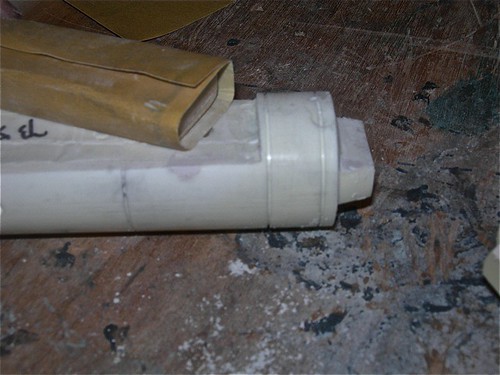
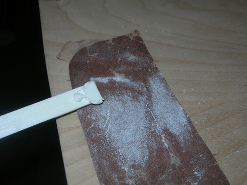
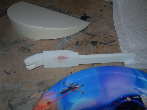
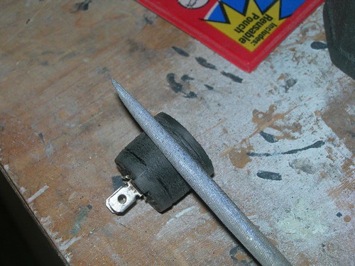
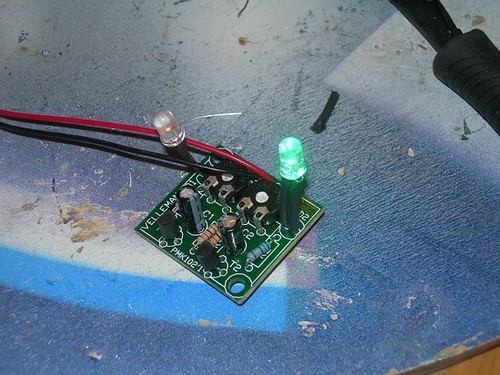
I also created another cool science fiction worm.

Sunday, November 28, 2010

Outer Foot Shell Channel Work

Today I spent a few minutes working on the center foot channels on the outer feet.


Due to the flat-pack nature of the A&A foot shells, the channel area of the front and back sides of the outer foot shells needed to be evened out with the aluminum channel piece.


Nothing that the file and a little sanding can't handle.


Now things look more even. Repeat three more times for the other faces.


The foot strips line up nicely with the flattened edges as well.


I may do some minor clean-up work on these, and I need to decide if I need to do somewhat of the same thing for the center foot shell.

Saturday, November 27, 2010

Foot Strip Cutting at Mike's

Today I went to Mike's to get the aluminum foot strips cut. There are two strips on each foot, six total. Each end has a differently angled cut on them, and Mike's chop saw is the perfect tool for the beveled edges.

Here is the most misleading picture of the day. Of the 12 cuts that were made, I probably succeeded with three or four. Mike either made the other cuts, or at least cleaned up the other ones I did. Apparently I don't hold the work very still as I'm cutting into it.


The camera managed to capture the teeth of the blade as they chop into the aluminum. Lots of small flakes of aluminum go flying about during the cut.


The 55 degree cut on the outer foot strips required a bit more elaborate setup. Mike clamped the work so that it would lay 90 degrees offset from the standard position, and then we set the miter angle to 35 degrees, and cut out 55 degrees' worth of material.


Looking good!


I still need to drill the holes for the knurled fittings on the front outer foot strips, and I may need to file or sand the center foot strips to be just a bit shorter once I square off the channel area on the center foot.

Friday, November 26, 2010

More Resin Parts Work

Today I spent some time finishing up the filling and sanding that I began a couple of days ago on various resin parts.

I sanded the Evercoat on the battery box harnesses and ankle cylinders smooth.


The half moon that I worked on earlier was less cooperative. After sanding down the first application of Evercoat, I could still see some areas that needed filling.


So, fill I did.


And sand some more I did.


That's better.


I think all the parts are ready for primer now. But first, I have some aluminum to chop.

Wednesday, November 24, 2010

Resin Parts Work

Today I emerged from Lazy Mode long enough to do a little prep work on some of my resin parts.

I hadn't yet washed the battery box harnesses, and some of the other resin parts needed a rinsing as well, so I (re)cleaned several parts.


The battery box harnesses each have a blob of resin on the bottom of the back side that need to be sanded off. A couple of the harnesses also need some filling work, due to bubbles taking a bite out of the corners.


A few minutes with 100 grit sand paper smoothes out the back of the harnesses.


Next, I gathered up all the parts that needed some filling work. I'm not going to fill the large void at the top-center of the ankle cylinders, since those are covered by the cylinder wedges.


I filled the bubbles in the corners of a couple of the harnesses.


The bottom edge of one of the half moons had some small wavy areas that needed to be filled. This is the problem child from May 5, 2010.


The first pass is done. Soon I'll sand the Evercoat smooth, and check to see if I need to make a second pass. I almost always do, so I'm expecting some minor additional work.

Wednesday, November 17, 2010

Widened Lower-Left Hole for Eye on Dome

Well, now that the screws have been glued into the back of the eye, I tried fitting the eye onto the dome.

Three of the four screws are happy, but the screw on the lower-left hand corner is the trouble-maker. For whatever reason, it doesn't quite hit the matching hole on the dome.


I debated whether to pull the screw out, fill, and redrill, versus just slightly widening the hole on the dome. The only downside to widening the hole on the dome is that it's pretty much a permanent modification, but it's also pretty much guaranteed to solve the problem. Relocating the screw in the eye might still not result in a perfect match, so I decided to gouge the dome hole by an additional millimeter or two.


Now, all four screws in the back of the eye fit their respective holes.


Lots of painting in my future, including the eye.

Tuesday, November 16, 2010

Glued Screws Into Back of Eye

Tonight I glued the screws into the back of the resin eye.

I'm using medium thickness CA glue.


Short and sweet, unlike the bulk of my updates.


The two top holes are slightly "irregular," due to drilling into a steep slope on the back of the eye when it was on the drill press. If I find that the screws want to come loose, I will pull them out and JB Weld them in place. Hopefully this will hold as-is, though.

Monday, November 15, 2010

Drilled Mounting Holes for Ankle Details

Tonight I drilled the backs of the ankle details, to accommodate the toothpicks(!) that I will use to mount them to the legs. I didn't drill the matching holes on the legs yet, because I haven't painted the legs, and I don't want to drill small holes now, only to gunk them up with paint later.

I dug out my old paper drilling template


I taped the template onto the back of the resin ankle detail, and got to drilling. I'm using a #43 (0.0890") drill bit that matches my toothpick selection. I drilled about half way deep into the resin.


The toothpick fits snugly. This works surprisingly well, I've had the ankle details held on this way on droid #1 for over three years and they are holding fast. I got the idea from Mike Senna, and his ankle details have been good for something like eight years.


Sixteen holes later, and I'm done.

Sunday, November 14, 2010

Trimmed Screws for Radar Eye, Fit Switches Into Dome, Masked & Primed Dome Ring, Swapped Green LED on Rear PSI

Today I took care of several minor, miscellaneous tasks.

First, I cut the heads off the four 1.5" #4 screws that I'm using to mount the radar eye onto the dome.


I will glue these into the back of the resin eye soon.


Next, I sanded the threads off the switches I'm using for the dome bumps, that double as on/off switches for the dome electronics.


I used a small file for the threads closest to the collar.


As with droid #1, the fit is nice and snug. These won't be coming out on their own, they need to be pushed out from inside. Obviously, they still need to be painted, but I wanted to finish the work on them before painting.


The weather was nice today, so I wanted to at least get the dome ring primed. I sanded the part of the ring that gets painted with 320 grit sand paper to remove the oxidation, and then I cleaned it up with acetone. Then, it was on to masking. Shiny!


I applied four coats of Rustoleum Painter's Touch white primer. I use white primer for areas that get painted blue. I will sand this smooth with 400 grit sand paper prior to painting.


Finally, because I can't seem to go more than a few days without swapping LEDs on the PSIs, I swapped an LED on a PSI. The pictures and video I displayed the other day of the rear PSI showed the green LED on the rear PSI looking more like an aqua-blue/green. I didn't like that, so out came the LED and its resistor.


In its place I put a 5Vf, 25mA "True Green" (as the package said) LED, and along with it, a 160 Ohm resistor. This really does look like true green in person, and unless I blow something up, I'm done goofing around with the LEDs.